

Fresnel reflection is identifiable by the spikes in an OTDR trace. When the light hits an abrupt change in index of refraction (e.g., from glass to air) a higher amount of light is reflected back, creating Fresnel reflection, which can be thousands of times bigger than the Rayleigh backscattering. The second type of reflection used by an OTDR-Fresnel reflection-detects physical events along the link. Higher wavelengths are less attenuated than shorter ones and, therefore, require less power to travel over the same distance in a standard fiber. When hit, some particles redirect the light in different directions, creating both signal attenuation and backscattering. This phenomenon comes from the natural reflection and absorption of impurities inside optical fiber. Rayleigh backscattering is used to calculate the level of attenuation in the fiber as a function of distance (expressed in dB/km), which is shown by a straight slope in an OTDR trace. Note that there are two types of light levels: a constant low level created by the fiber called “Rayleigh backscattering” and a high-reflection peak at the connection points called “Fresnel reflection”.


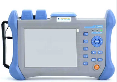
Learn all about OTDR testing and EXFO's OTDR products Reflection Is KeyĪs previously examined, the OTDR provides a view of the link by reading the level of light that returns from the pulse which was sent. The main advantage of using an OTDR is the single-ended test-requiring only one operator and instrument to qualify the link or find a fault in a network. Therefore, many acquisitions will be performed and averaged in a second to provide a clear picture of the link’s components.Īfter the acquisition has been completed, signal processing is performed to calculate the distance, loss and reflection of each event, in addition to calculating the total link length, total link loss, ORL and fiber attenuation. When the pulse has entirely returned to the detector, another pulse is sent-until the acquisition time is complete. As the pulse travels along the fiber, a small portion of the pulse’s energy returns to the detector due to the reflection of the connections and the fiber itself. A clock then precisely calculates the time of flight of the pulse, and time is converted into distance-knowing the properties of this fiber. The signal sent is a short pulse that carries a certain amount of energy. This produces a trace on a graph made in accordance with the signal received, and a post-analysis event table that contains complete information on each network component is then generated. The laser source sends a signal into the fiber where the detector receives the light reflected from the different elements of the link. Return to glossary The Fundamentals of an OTDR The BasicsĪn OTDR combines a laser source and a detector to provide an inside view of the fiber link.


 0 kommentar(er)
